 Index
IndexThe Tarquin Extruder Builder Brush
I would like to show you a powerful and easy-to-use builder brush that everyone should know:
Yes, it is really easy to use. No no, really, once you get over the many options with strange and impressive names, you will see that it is actually an intuitive builder brush which can save you a lot of time.
The Tarquin Extruder Builder Brush works by drawing a polygon, placing its vertices, then entering several points defining a path along which the shape is extruded, allowing you to easily and quickly create pipes, wires, borders or tunnels. It also makes texturing much easier by keeping a texture more or less cleanly wrapped on the surfaces of the resulting brush.
The Tarquin Extuder Builder Brush was last updated by Tarquin in may 2001, and it is both ancient and widely unknown, like most custom UnrealEd tools. This is a shame and has to change. Despite Tarquin declaring it still at the "experimental stage" at the time it was released, it is perfectly stable and can be used with no risks.
1. Where to find it and how to install it ?
Since the demise of all the PlanetUnreal websites and the subsequent vanishing of Tarquin's website, the original links and tutorials by the creator of the tool itself are lost. Fortunately, the tools themselves are still widely available through hosting sites. You can download the Tarquin Extruder Builder Brush at the bottom of this page, choosing the one corresponding to the game you want to use it with. The UT99 tools work with UnrealEd 2.0 and 2.1 for Unreal with the 227 pack, but I have no clue if they work with the ancient and deprecated UnrealEd 1.0 which, as far as I know, uses a completely different system.
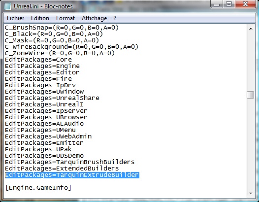
Once the file is downloaded and unzipped, put the BBTarquinExtrude.bmp file in System\editorres folder of your Unreal Directory, and the .u file into the \System folder. Then, open Unreal.ini/UnrealTournament.ini/UT2004.ini (or any other variation depending on the game you are using) with a text-editing software and search for the EditPackages= lines; there should be a bunch of those in the middle of the file, in the [Editor.EditorEngine] chapter. At the end of this list, add the line EditPackages=TarquinExtrudeBuilder, save and close.
This will tell UnrealEd to search and process the TarquinExtrudeBuilder.u file the next time you open it, and the tool will thereafter be available. Now, launch UnrealEd. The TarquinExtruderBuilderBrush (from now on contracted as TEBB), is available under the usual builder brushes as a purple snake-like tool.

2. How does it work?
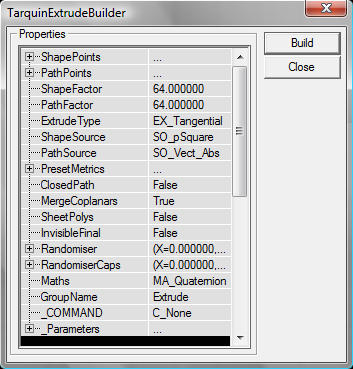
Right-click on the tool to open the truckload of properties shown earlier. If you try left-clicking on it, you should see a popup window explaining that you need at least two PathPoints. We will see why later.
The two most important properties of the TEBB are the ShapePoints and PathPoints lists. Each list can contain up to 16 (0-15) points to define a shape and a path along which to extrude it. Under these two are the ShapeFactor and PathFactor, defaulted to 64. These two parameters how long "1" is in Unreal Units in the lists. For example, drawing a square shape to be extruded along a path means you will need 4 points with coordinates along the lines of 000,100,110,010 on a XYZ setting:
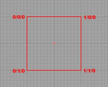
In this case, a point with the coordinates X=0, Y=1, Z=0 will be placed 64 units away from the brush's pivot on the Y axis if ShapeFactor is set to 64. Likewise, if the path calls for the shape to be extruded on "4" along the X axis, the shape will be extruded along 4*64=256 units. Of course, you can set non-integers as an input value, like 0.5 to move a vertex 32 units away instead of 64. It also means you can easily double of halve the scale of a brush by halving the ShapeFactor, or its path with the PathFactor.
The 0,0,0 point is the position of the pivot of the brush. Usually, the pivot will thus be blended with your first vertex (which is at coordinates 0,0,0 by default too), but you can also decide to put your first vertex on another position, with the pivot clearly distinguishable from it. It should not be very useful in most cases though.
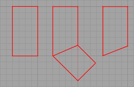
Under the Factors is the ExtrudeType parameter. EX_ThirdWay and EX_Tangential seem more or less similar, but EX_Transational is quite different. Using Tangential and ThirdWay usually results in the shape being rotated appropriately to face the path, and then extruded lenght-wise. This means the shape will always be facing (at each point of its path) the next point, each part of the "snake" will have the same width, and corners will be nicely defined:
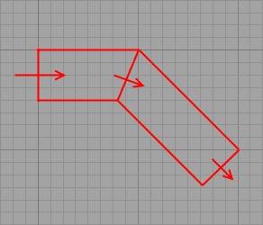
This image is taken in the TOP viewport. Though the shape is defined on the X/Y plane, the brush is rotated in order to face the direction of its path, and drawn on an Y/Z plane instead. Notice how the bend is elegant and balanced, the shape itself always facing its next direction. Now, if we change this to EX_Translational :
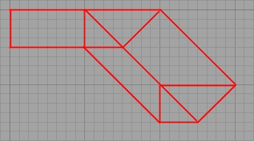
It is translated into a bloody mess of vertices and edges. Why? The shape is a trapezoid on the X/Y plane translated solely on the XY plane. If we analyse the brush, we can see that what we have is precisely what we asked for:
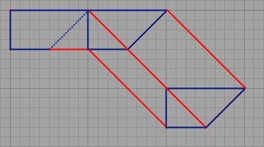
Notice in blue the three successive positions of the original shape which is translated but never altered or rotated. In order to have a better result, the shape should not be defined on the X/Y plane but on the Y/Z plane, so that it would face the direction of the first part of the path. Where the shape would bend, a translational extrusion will keep the same polygon and only translate it: move all of its points to the new position and link them to the previous stage. Tangential and Third way, on the other hand, will make a nice bend and allow the shape to be of equal width at each point. Most of the time, Tangential is preferable, but some cases could occur where Translational may come in handy.
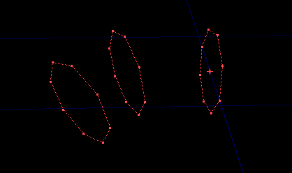
Under the ExtrudeType, ShapeSource allows you to choose between 3 basic shapes: square (with each vertex separated by 1, so adjust you ShapeFactor), Circle, a 8-sided circular shape that can be used for tubes, pipes or tunnels, MrPointy, which is a complex shape made of two crossing arrows (better used as a way to remember which axis is X or Y or Z), and finally, Vectors, which allows you to define a shape with the vertices set in ShapePoints. By default, this setting is set to SO_Square, so if your new shape seems to be ignored, take a look there. Right under it is PathSource. This important parameter defines what each PathPoint (set into the PathPoints list) is relative to. By default, this parameter is set to SO_Vect_Abs(olute); in this case, each PathPoint will be defined relatively to the origin of your brush. SO_Vect_Rel(ative), on the other hand, means each PathPoint is relative to the previous PathPoint in the list:
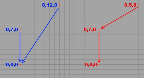
As you can see here, the blue set shows three points with their coordinates relative to the origin of the brush (the 0,0,0 point): they use Absolute coordinates. The second vertex is only "7" away from the origin on the Y axis, but the third is distant from the origin by "12" on the Y axis and "8" on the X axis. The red setting has relative coordinates: each vertex is defined by the position of the previous one: the second vertex is still distant from the origin by "7" on the Y axis, but the last vertex is 8X and 5Y away from the previous vertex: its position is not defined by the position of the origin but by its predecessor in the list.
Both methods have pros and cons. Absolute coordinates allow you to adjust part of your brush without affecting other sections of it, while any change to any point in the relative setting will change the position of all subsequent PathPoints. However, relative vectors are easier to compute and handle. What setting to use is a matter of opinion and situation.
PresetMetrics is an array that ties in with the ShapeSource parameter. When using the predefined Square, only the 0,1,2 and 3 fields are taken into account; 0 determines the breadth of the square on the X axis, 1 determines its width on the Y axis. These numbers are multiplied by the value of the ShapeFactor property to create the original polygon. PresetMetrics 2 and 3 are used to offset all vertices on the X and Y axis.
Now when using a Circle ShapeSource, Preset 0 is the number of sides of the full circle. Note however that going above 16 will give you increasingly incorrect results, with a portion of the circle obviously cut. PresetMetrics1 defines how many of these sides are actually used: this allows you to create only semi-circular shaped (or a quarter of a circle etc.); 2 and 3 are still offset settings on the X and Y axis, but now, PresetMetrics 4 allows you to chose if the cylinder is "aligned" (1) or not (0). An "aligned" cylinder is built differently (you can try this on a normal cylinder to understand the effect).
ClosedPath is also a very important setting: if your shape has at least three PathPoints, you can set this property to true and the last PathPoint will automatically be linked back to the origin, creating a ring-like shape. This is very useful but requires at least three PathPoints, as the TEBB will otherwise refuse - rightly so - to build a faulty brush.
MergeCoplanars is exactly what it says on the tin: say you have a long extruded tunnel with no height variation; the floor will be made of as many coplanar faces as there are sections of the path. This parameter, if set to true, will merge these faces into one,giving better lighting and texture alignment.
SheetPolys will create a brush with only sheets: the brush will be visible from the inside and the outside, will not have caps and will have no collision. This setting is of limited interest.
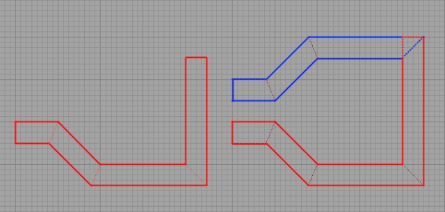
InvisibleFinal is a tricky function: it will build the brush according to your path, but will not build the final section. What makes this setting useful is that it allows you to end your brush with something else than the usual cross-section of your shape: the last part of your shap will be bended, as if another PathPoint was computed but not joined:
From left-to-right, a normal shape with two points, the same with a third point added, and finally the second shape with InvisibleFinal. As you can see, the last section is not drawn but the last visible section is bended accordingly.
The two next parameters, Randomiser and RandomiserCaps can be used to randomise slightly the position of the vertices along the path : by entering a value (for example 0.5) in a field, all vertices will be randomly increased by a number between 0 and 0.5 on the selected axis. The Randomiser settings affect vertices along the path, while RandomiserCaps values affect only the vertices of the shape at the beginning and end of the path.
Maths determines how the path is computed. Because no "official" documentation remains, its effects are mysterious, but it is better to leave this one to MA_Quaternion, as Matrix is known to cause some problems.
GroupeName is an unimportant parameter that defines the name of the group to wich the created brush is added. Finally, _COMMAND contains a variety of useful commands to be activated when clicking "Build". C_None is default inactive. C_ResetPath and C_ResetShape are by far the most useful ones as they allow you to reset completely the PathPoints and ShapePoints lists on build (by setting all their values to 0, instead of having you enter all these zeros by hand). C_ShowShape will create the shape as a 2d sheet, which is useful in the first stage of the creation of a new brush by allowing you to see precisely what it looks like before setting a path. C_ShowJoint creates only the joints, the shape itself, on each bend of its path:
C_MoveShape, C_ScaleShape and C_RotShape will respectively offset, scale and rotate the shape according to the parameters of the _Parameters field. With Scale, Parameters 0 and 1 will define the factor by which the shape is scaled ont the X and Y axis. With Move, they will define how far the shape is offset on the X and Y axis. With Rotate, only Parameters 0 is useful and will define by how many degrees the shape is rotated. Note that contrarily to all UnrealEd customs, this is done with real degrees (180 being a U-turn) and not UnrealEd degrees (with 65536 being 360°).
C_MakeArc could work much like the revolve tool of the 2DShape Editor, but does not: it is supposed to allow you to revolve your shape. You need at least three PathPoints to use it. The three last points of the shape are used to determine the revolving in a mystical way that can only been described as a masochistic mathematical computation. I will let Tarquin's description speak for itself:
"The builder looks at the last three PathPoints; call them A,B,C in order, so C is the very last PathPoint. The arc will start at point A. B and C are used for information about the size and orientation of the arc and will be over-written.
B is taken to be the centre of the arc, and C is a point 1/4 of the way around the full circle. Another way of looking at it is that line AB goes from 12 o'clock to the centre of the clock face, and BC from the centre to 3 o'clock.
Note that if these two lines are of different lengths the arc will be a piece of an ellipse rather than a circle."
Long story short, the three last PathPoints are used to set, in that order: 1) The last position of your current shape. It acts as the orange vertex in the 2DShape editor: the center of the brush; 2) The center, or pivot, around which to revolve the arc. It acts as the green pivot in the 2DShape Editor; 3) A point arbitrarily set as a quarter of a complete circle.
The MakeArc tool also uses the _Parameters fields: 0 is the number of sides for 360°, 1 is the number of sides used, and 2 allows you to choose between "aligned" (1) or not (0).So if you set in 1 a value which is a quarter of the one you set in 0, you will have a quarter of a circle, starting in A, ending in C and revolving around B. If you set 1 to be a half of 0, you'll have a semi-circle and C will be precisely in the middle of it, etc. As Tarquin points out, if AB and BC have unequal lengths, your "circle" will have more width than length (or the other way round), and you'll have an ellipse.
Finally, the C_MakeMirror function allows you to mirror all your existing points from the last PathPoint you set:
_Parameters0 can be used: it will decide what happend to the last section of the brush. When set to 0, the last section of the brush is deleted completely and the two halves are joined together at an angle equivalent to the one they would have if the last section was between them. If set to 1, the last section is preserved : the mirror image starts at its end. If set to 2, the last secion is itself mirrored; the last section is doubled in fact, and then the mirror image is added.
Now that you have gone through all these complex parameters with intimidating names, it is time to start using them. We will see only a couple of basic functions, those you are most likely to use. Very advanced and complex things can be done with it, but once you feel the need to use them, you should be UnrealEd-savvy enough to mess around with the TEBB with me holding your hand.
3. Using the Tarquin Extruder.
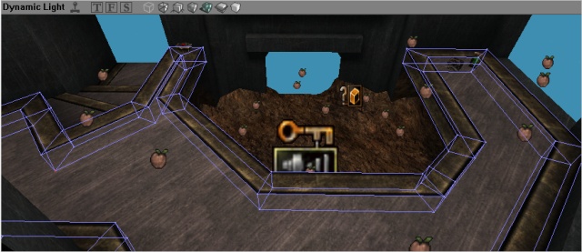
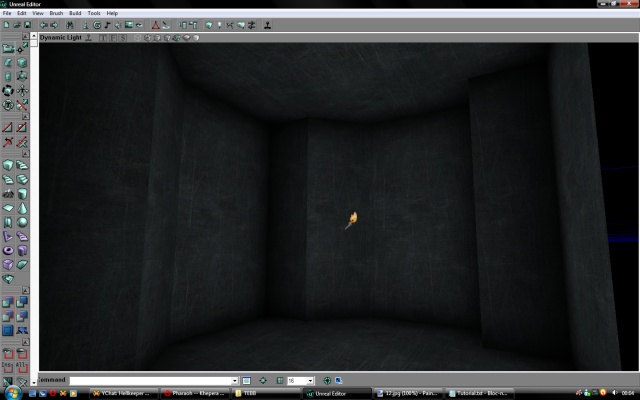
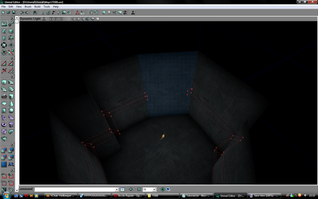
Take a look at this scene:
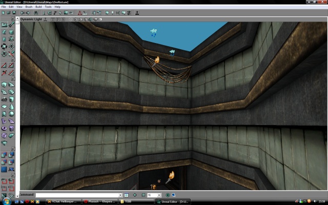
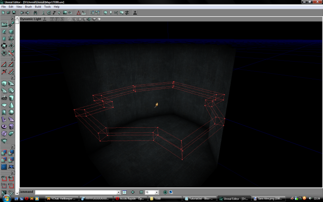
The map is DmRiot. Most of the structures here (the windows, the borders), run all around the room and are closed shapes. This is the exact type of situation where you would want to use the TEBB : long borders with many bends, eventually closing in on themselves. Let's make such a room to take advantage of our great tool:
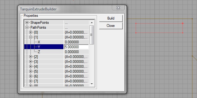
Imagine you need a border or trim to run around the room. It would be a square-section shape extruded along the walls. We want the trimming to be 32 units high. First, opening our TEBB, let's choose a ShapeFactor of 32. We have no idea what angles or distances we might need for the room, so let's use a PathFactor of 32 too, small enough to be precise, yet high enough not to have to enter huge numbers. ShapeSource can be left to Square, and because we will do nothing fancy, set PathSource to SO_Vect_Rel. Before hitting "build", we need to enter at least two PathPoints. The first one can be 0,0,0, but because we need another, set PathPoint [1] to 0,5,0:
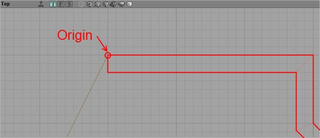
Notice te side of the brush on which the pivot is located. In my case, it is in the upper-left corner. This is important because when bending the shape some vertices will be taken off the grid to keep the shape the exact same width on its angled sections:
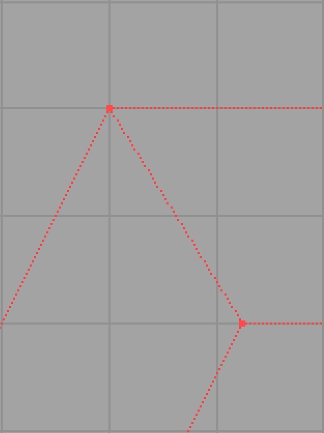
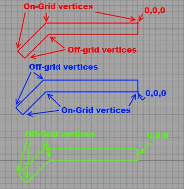
On this picture, you can clearly see that the vertex (vertices, actually) inside the bend are off the grid, while those on the outside of the bend are still snapped neatly. This is mostly determined by the way your brush is built: all vertices on the side of the origin (the 0,0,0 vertex) will be aligned, while those on the other side will be off the grid. If you have offset your shape so that the origin is not on the same coordinates as a vertex, all vertices may be off the grid:
In my case, I want the snapped side to be the outside of the border, so that it fits perfectly with the walls, so that it will be protuding 32 units into the room itself. Because we will be working with X/Y coordinates, it is preferable to make sure the rotation of your builder brush has been reset before entering the first coordinates : right-click on the brush (make one if needed by clicking the Cube Builder Brush) and click Reset => Reset Rotation (or even Reset All). Then, in your PathPoints, letting 0 to his original 0,0,0 coordinates, set X=5 in 1. The brush should stretch from his origin to the right. Put the origin inside your room in a corner:
From now on, your work is only a question of adding successive coordinates to the PathPoints until it loops back to the corner before your origin. Coordinates can be negative and non-integers: when your PathFactor is 32 and you need to stretch your brush only 16 units in a given direction, you can just input 0.5 on the needed axis. After a few try, PathPoints will start to come naturally to you.
Once you only need one segment, instead of having the brush loop on itself through PathPoints, simply set ClosedPath to True and hit build. The last segment will automatically be created by linking the beginning and end of the brush.
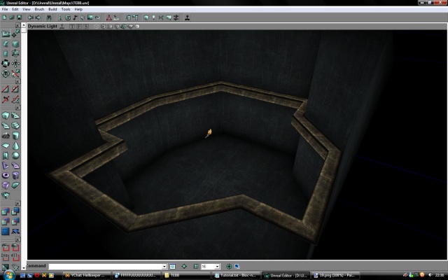
Add it and apply a texture. You will notice it already fits nicely (a 90° rotation may be needed as in my case).
4. That was fun, what's the downside?
The benefits of the Tarquin Extruder Building Brush are many: the ability to quickly create large complex trims with no effort required to fit and align textures can really speed up the building of a map. It allows you to fit perfectly a given width on such beams and borders which means you don't need to make precise assessment of the scaling to be applied on such and such axis of the texture. It also means you will use less brushes, making modifications of large rooms easier. Selection will be easy in all viewports. Much less time will be devoted to painfull vertex-editing of the same brush over and over again to meet the edges of a room or doorway. You can also easily create wires with curves and such. All in all, the TEBB is a great tool.
What you should remember is that the TEBB will create brushes with several vertices completely off the grid, which may complexify and disturb the BSP cuts of a room. Having too many of such brushes piled on top of each other in a room with an already imbalanced brushwork will result in BSP corruption, HOMs, BSP holes, invisible polys and other such artefacts. Though you cannot do much about it, it should force you to use clean, ordered and aligned BSP snapped to the grid to limit possible troubles. If your basic brushes are sane, extensive usage of the TEBB should not be problematic.